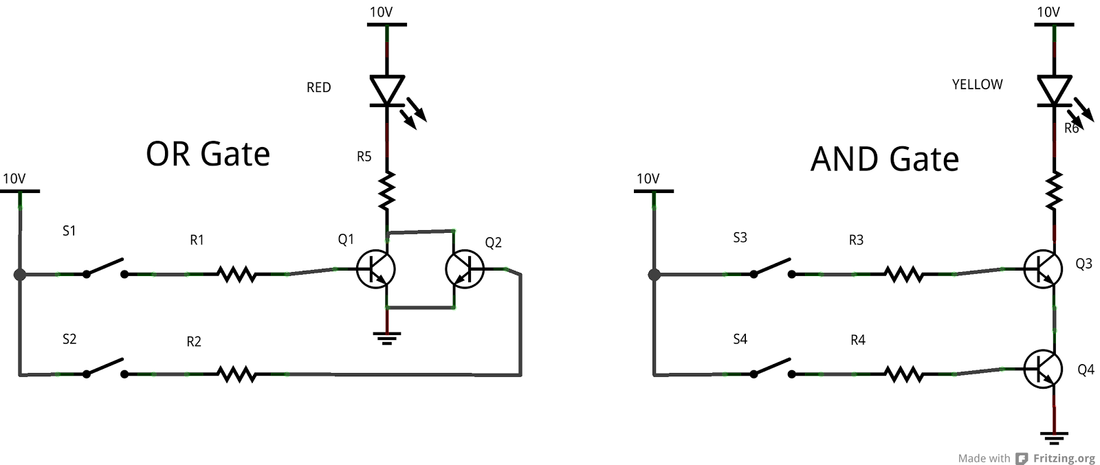
Diode And Gate Circuit Diagram
Working of or gate using diode Diode and gate (w subtitles) 14+ and gate circuit diagram using diode
Explain Logic OR Gate and Its operation with Truth Table - Electronics Post
Introduction to and gate Gate nand circuit diode using logic gates dtl transistor gif junction any Diode logic gates
Diode diodes
14+ and gate circuit diagram using diodeCircuit decoding diode schematic gate two seekic shown follow Gate circuit diagram diode logical electrical4u diodes principle working reverse biasGate circuit diode diagram electrical4u diodes 5v apply principle working above first.
What are logic gates? or, and, not logic gate with truth tableGate diodes using diode logic circuit resistor resistors gates question Circuit diodes principle switchesCircuit analysis.

Gate diode
Gate logic circuit diode using gates diodes not two voltage 5v figure hereGate diode using circuit diagram And gate: what is it? (working principle & circuit diagram)Logic and gate tutorial with logic and gate truth table.
Diode circuit diagram introduction engineersgarageCircuit basic seekic Diode as a gate tutorial and circuitsGate diodes logic truth table explain using operation its fig.

Logic gates circuit
Diagram circuit clamp gate diode output has seekic shown followDraw the circuit diagram of and gate using diodes. Gate diode electronic tutorial shuts remainder reject signal opens let then through partXor diode diodes transistors logic circuitlab transistor bipolar hackaday.
Gate transistor logic input gates transistors truth table inputs circuit circuits digital output structure tutorial diagram using two ttl electronicsAnd gate: what is it? (working principle & circuit diagram) 14+ and gate circuit diagram using diodeNand gate using diode circuit.

Diode logic gates lab theory resistor
Logic circuit gates diode analysis diodes using stack electrical implemented me drl gifOutput has a clamp diode gate circuit diagram Explain logic or gate and its operation with truth table.
.


14+ And Gate Circuit Diagram Using Diode | Robhosking Diagram

Explain Logic OR Gate and Its operation with Truth Table - Electronics Post

logic gates circuit - Theory articles - Electronics-Lab.com Community

Index 101 - Basic Circuit - Circuit Diagram - SeekIC.com

14+ And Gate Circuit Diagram Using Diode | Robhosking Diagram

AND Gate: What is it? (Working Principle & Circuit Diagram) | Electrical4U

What are Logic gates? OR, AND, NOT logic gate with truth table

Diode Logic Gates